Product Description
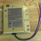
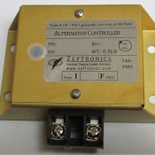
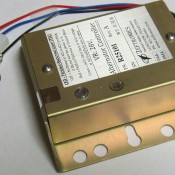
28V Alternator Controller Unit (ACU)
What’s included:
- Installation Drawing
- CTA7 for Cessna Installations
- STC Certificate
- Warranty Card
- Product Eligibility Catalog (PEC)
- Troubleshooting Notes
- Instructions For Continued Airworthiness Maintenance (ICA)
Product Features:
Voltage Regulation, IC Sense reference
The Voltage Regulator keeps the bus voltage constant by increasing the current to the alternator’s field with a system load increase, decreasing it with a load decrease.
Field-to-Ground Fault Protection (GFP)
If the alternator’s field become shorted to ground, the GFP will deactivate the Voltage Regulator, and switch on the unit’s Red TSL, and the LVI light on the instrument panel.
Built-In Alternator Out Indication / Low Voltage Sensor (LVI)
The unit has a true Low Voltage Sense and Indication as opposed to the current Cessna Aircraft setup. The LVI will illuminate (turn on) under these conditions:
- Bus voltage drops below the Low Voltage level
- Over Voltage Protection Trip
- Field-to-Ground Short Fault Protection Activated
- Open alternator field (internal) or broken field wire
- Loss of power to the ACU
Battery Off-Line Failure Regulation (BOLR)
The design of the ACU allows it to excite the field of a rotating alternator (with a minimum residual voltage) and regulate the bus voltage with the battery off-line. This allows the system to carry electrical load if the battery fails or the battery relay fails (open).
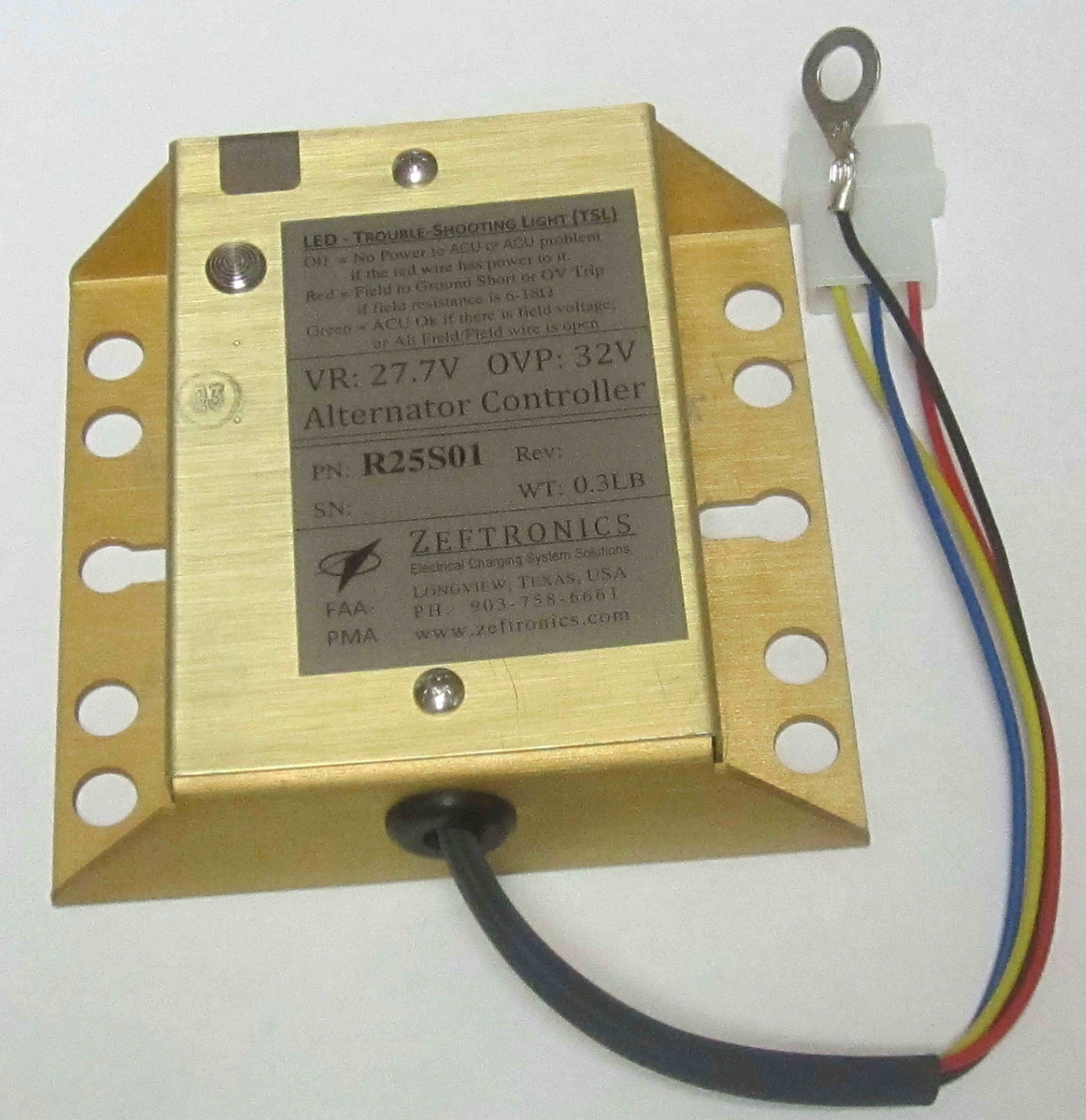
Trouble-Shooting Light (TSL)
TSL: RED with the Bat & Alt switches on means there is an internal or external ground short in the alternator field circuit.
TSL: GREEN with the engine running, means there is power coming out of the ACU.
TSL: GREEN with a bus voltage of 27.3V to 28.1V indicates a system that is operating correctly.
TSL: GREEN with a sustained bus voltage of 20V to 25.6V means current is flowing from the ACU, but the alternator field or field wire to it is open.
TSL: OFF with the Master switch on and no power to the ACU (red wire), means that one power input device (like switch, circuit breaker, or wiring) is open.
TSL: OFF with the Master switch on and power to the ACU (red wire), means the ACU is damaged.
Other Features:
- Voltage Regulation (VR), IC Sense Reference
- Increased Regulator life. Reduced panel lights flicker
- Protects against grounded Alternator field
- ACU controls & keeps the Alternator on-line if the Battery fails
- Protects system loads against overexcited Alternator
- Reduce trouble-shooting time, Cost-Saving Solution!